Description
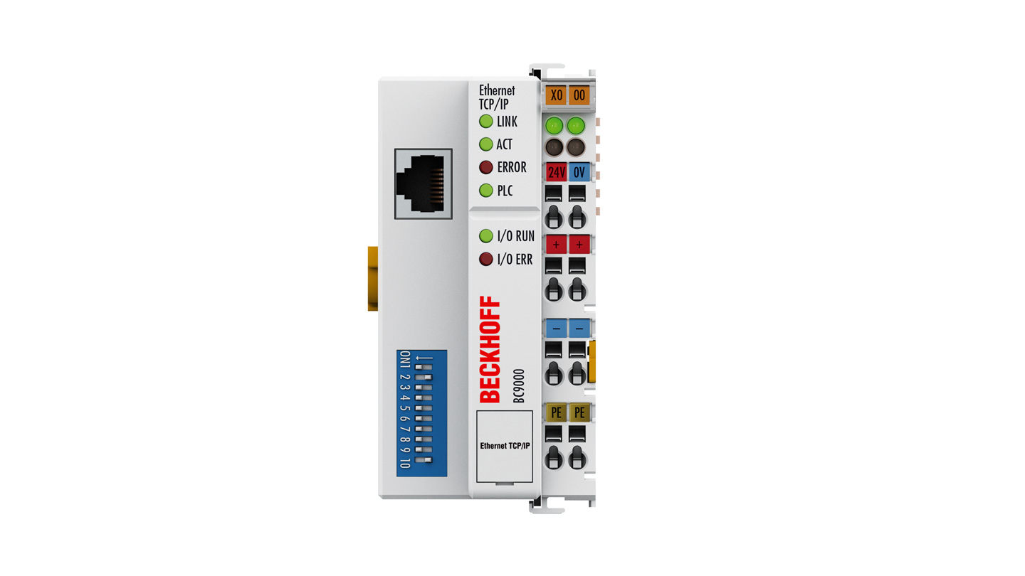
BC9000 | Ethernet TCP/IP Bus Terminal Controller
The BC9000 Bus Terminal Controller is a Bus Coupler with integrated PLC functionality and has a fieldbus interface for Ethernet. It is an intelligent slave that can be used as a non-central intelligence in the Ethernet system. One unit consists of the Bus Terminal Controller, any number of terminals between 1 and 64, and a bus end terminal.
The Bus Terminal Controller is programmed using the TwinCAT 2 programming system according to IEC 61131-3. The configuration/programming interface of the BC9000 is used for loading the PLC program. If the software PLC TwinCAT is in use, the PLC program can also be loaded via Ethernet.
In the default setting the inputs and outputs of the connected Bus Terminals are assigned to the controller. Each Bus Terminal can be configured in such a way that it exchanges data directly through the fieldbus with the higher-level automation device.
Controller for distributed signal processing
The BC9000 and BC9050 Bus Terminal Controllers support the operation of all Bus Terminal types. As far as the user is concerned, the inputs and outputs are not handled any differently from the way they are by other coupler series. The information is made available for use as a byte array in the process image of the automation device.
The analog and multi-functional Bus Terminals can be adapted to each specific application using the KS2000 configuration set. Depending on the type, the analog Bus Terminals’ registers contain temperature ranges, gain values and linearization characteristics. With the KS2000, the required parameters can be set on a PC. The Bus Terminals store settings permanently and in a fail-safe manner.
Having the controller (PLC, IPC) carry out the configuration of the Bus Terminals is a further option. The PLC or IPC uses function blocks (FB) to take care of the configuration of all the peripherals during the start-up phase. The controller can, if required, upload the non-centrally generated configuration data in order to manage and store them centrally. This means that it is not necessary to carry out the setting procedure again if a Bus Terminal is exchanged. The controller carries out the desired setting automatically after switching on.
Product information
| PLC date | Ethernet TCP/IP | BC9000 |
| programming | via TwinCAT and programming interface or Ethernet |
| Program memory | 64/96 kbytes |
| Data memory | 64/128 kbytes |
| Remaining date | 4080 bytes |
| Runtime system | 1 task PLC |
| PLC cycle time | approx. 1.5 ms for 1,000 instructions (without I/O cycle, K-bus) |
| Programming languages | IEC 61131-3 (IL, LD, FBD, SFC, ST) |
| Online change | – |
| Technical data | BC9000 |
| Number of Bus Terminals | 64 |
| Max number of field bus bytes | 512 bytes input and 512 bytes output |
| number of bytes process image | 512 bytes input and 512 bytes output |
| Digital peripheral signals | 512 inputs/outputs |
| Analog peripheral signals | 128 inputs/outputs |
| protocol | TwinCAT ADS, Modbus TCP |
| Configuration possibility | via KS2000 or Ethernet |
| Data transfer rates | 10/100 Mbit/s, automatic recognition of the transmission rate |
| Bus interface | 1 x RJ45 |
| power supplies | 24 V DC (-15 %/+20 %) |
| Input current | 70 mA + (total K-bus current)/4, 500 mA max. |
| Starting current | 2.5 x continuous current |
| Recommended fuse | ≤ 10A |
| Current supply K-bus | 1750mA |
| Power contacts | max. 24V DC/max. 10 A |
| Electrical isolation | 500V (power contact/supply voltage/fieldbus) |
| Weight | approx. 170g |
| Operating/storage temperature | -25…+60°C/-40…+85°C |
| protect. rating/installation pos. | IP20/variable |
| Approvals/markings | CE, UL, ATEX, DNV GL |
| Ex marking | II 3 G Ex nA IIC T4 Gc |
| Housing date | BKxxxx, BCxxxx |
| Form design | compact terminal housing with signal LEDs |
| Material | polycarbonate |
| Dimensions (W x H x D) | 51mm x 100mm x 69mm |
| Installation | on 35 mm DIN rail, conforming to EN 60715 with lock |
| Side by side mounting by means of | double slot and key connection |
| Marking | labeling of the BZxxx series |
| Wiring | solid conductor (e), flexible conductor (f) and ferrule (a): spring actuation by screwdriver |
| Connection cross section | s*: 0.08…2.5 mm², st*: 0.08…2.5 mm², f*: 0.14…1.5 mm² |
| Stripping length | 8…9mm |
| Current load power contacts | I max : 10A |
*s: solid wire; st: stranded wire; f: with ferrules


Reviews
There are no reviews yet.