Description
EK1100 | EtherCAT Coupler
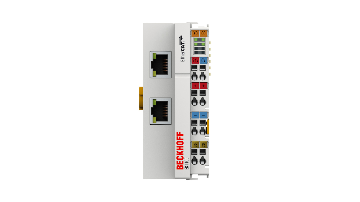
The EK1100 EtherCAT Coupler is the link between the EtherCAT protocol at fieldbus level and the EtherCAT Terminals. The coupler converts the passing telegrams from Ethernet 100BASE-TX to E-bus signal representation. A station consists of a coupler and any number of EtherCAT Terminals that are automatically detected and individually displayed in the process image.
Special features:
- Connection technology: 2 x RJ45 socket
- Connection lengths: up to 100 m
- Number of EtherCAT Terminals in the overall system: up to 65,535
The EK1100 has two RJ45 sockets. The upper Ethernet interface is used to connect the coupler to the network; the lower socket serves for the optional connection of further EtherCAT devices in the same segment. In addition, an EtherCAT junction or an EtherCAT extension can be used for the extension or for setting up a line or star topology.
The system and field supply, each 24 V DC, is provided directly at the coupler. The attached EtherCAT Terminals are supplied with the current required for communication from the supplied system voltage. The coupler can supply a maximum of 5 V and 2 A. If higher current is required, power feed terminals such as the EL9410 have to be integrated. The field supply is forwarded to the individual I/O components via the power contacts with up to 10 A.
In the EtherCAT network, the EK1100 can be installed anywhere in the Ethernet signal transfer section (100BASE-TX) – except directly at the switch. The EK9000 and EK1000 couplers are suitable for use at the switch.
Product information
| Technical data | EK1100 |
| Task within EtherCAT system | coupling of EtherCAT Terminals (ELxxxx) to 100BASE-TX EtherCAT networks |
| Data transfer medium | Ethernet/EtherCAT cable (min. Cat.5), shielded |
| Distance between stations | max. 100 m (100BASE-TX) |
| Number of EtherCAT Terminals | up to 65,534 |
| Protocol | EtherCAT |
| Delay | approx. 1 µs |
| Data transfer rates | 100 Mbit/s |
| Bus interface | 2 x RJ45 |
| Power supply | 24 V DC (-15 %/+20 %) |
| Current consumption from US | 70 mA + (∑ E-bus current/4) |
| Current consumption from UP | load |
| Current supply E-bus | 2000 mA |
| Power contacts | max. 24 V DC/max. 10 A |
| Electrical isolation | 500 V (power contact/supply voltage/Ethernet) |
| Operating/storage temperature | -25…+60 °C/-40…+85 °C |
| EMC immunity/emission | conforms to EN 61000-6-2/EN 61000-6-4 |
| Relative humidity | 95 %, no condensation |
| Vibration/shock resistance | conforms to EN 60068-2-6/EN 60068-2-27 |
| Protect. rating/installation pos. | IP20/variable |
| Approvals/markings | CE, UL, ATEX, DNV GL, IECEx, cFMus |
| Ex marking | ATEX: II 3 G Ex nA IIC T4 Gc IECEx: Ex nA IIC T4 Gc Ex tc IIIC T135 °C Dc cFMus: Class I, Division 2, Groups A, B, C, D Class I, Zone 2, AEx ec IIC T4 Gc |
| Housing data | EK-44-8pin |
| Design form | compact terminal housing with signal LEDs |
| Material | polycarbonate |
| Dimensions (W x H x D) | 44 mm x 100 mm x 68 mm |
| Installation | on 35 mm DIN rail, conforming to EN 60715 with lock |
| Side by side mounting by means of | double slot and key connection |
| Marking | labeling of the BZxxx series |
| Wiring | solid conductor (e), flexible conductor (f) and ferrule (a): spring actuation by screwdriver |
| Connection cross-section | s*: 0.08…2.5 mm², st*: 0.08…2.5 mm², f*: 0.14…1.5 mm² |
| Connection cross-section AWG | s*: AWG 28…14, st*: AWG 28…14, f*: AWG 26…16 |
| Stripping length | 8…9 mm |
| Current load power contacts | Imax: 10 A |
*s: solid wire; st: stranded wire; f: with ferrule

Reviews
There are no reviews yet.